
Receive the Truth into the Heart.
|
Receive the Truth into the Heart. |
|
DETAILED INDEX | CD | CHARLES FINNEY | ASA MAHAN BOOKSTORE | SHOPPING CART | GUEST BOOK | ADDRESS | DONATIONS |
For educational purposes only. Do not copy without
permission. Experiment lawfully at your own risk. John Bedini's "Simplified School Girl" Radiant Energy Oscillator and Energizer Motor
Bedini
Monopole Yahoo Group Project 2
SEE OLDER PAGE FOR PROJECT ONE CONSTRUCTION AND TESTING
Special thanks to John
Bedini for giving us these plans
and for making them easy for simple people!  Now selling John's book, a few DVDs and an SSG parts kit: rpmgt.org/order.html The following is the Yahoo forum we are using to discuss and build these machines: Some of the plans for building this device come from the following web site (not all information on that site is correct): peswiki.com/index.php/Directory:Bedini_SG The
theory and information behind this are found at the following John Bedini webs sites:
energenx.com/john1/index001.html, energenx.com/john1/intro.html,
energenx.com/john1/john1.html Energenx.com Products r-charge.com
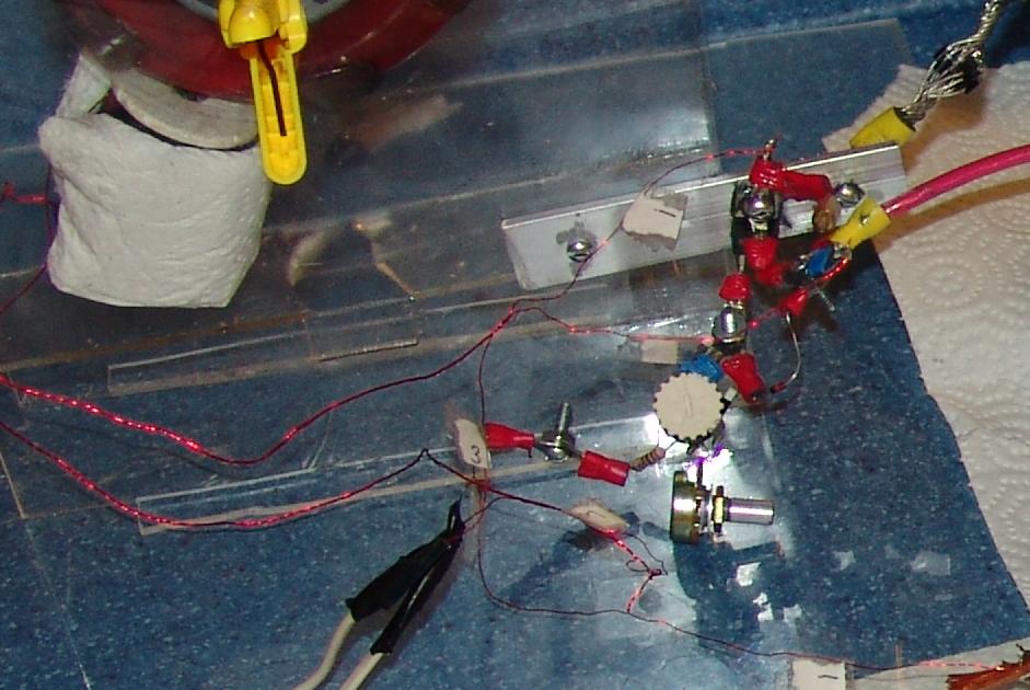
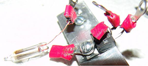
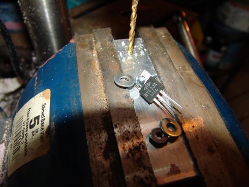
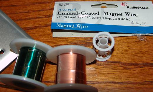
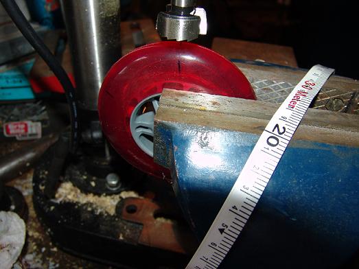
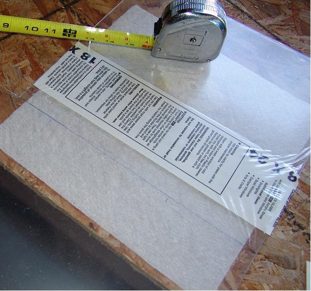
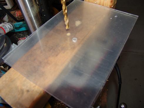
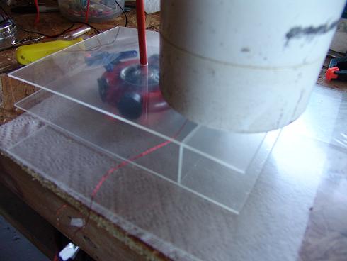
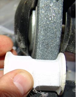
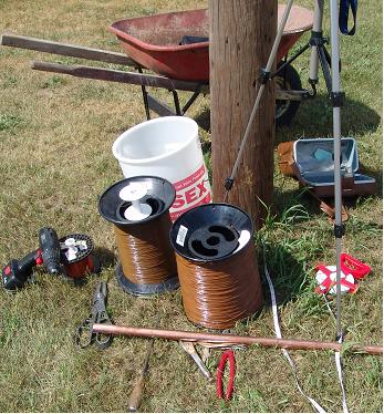
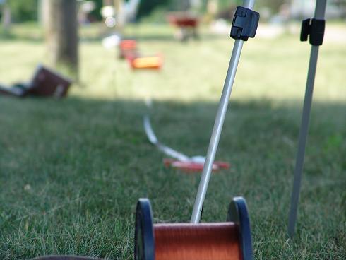
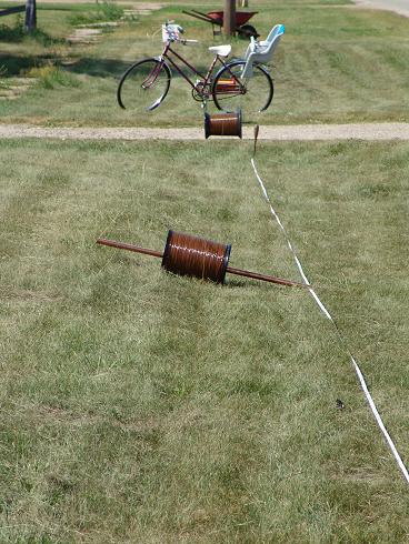
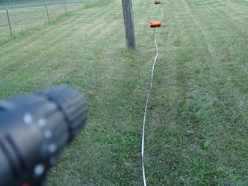
INTRODUCTION TO THIS PAGE: THIS PART BELOW IS OLD AND COULD NEED UPDATES. On this page we will show the progress, pictures, and videos of the complete construction and testing of the Group Project 2 Bedini Monopole Simplified School Girl (SSG) and Bedini Trifilar small scale Setups. I will try and make a more comprehensive introduction to what these are in the near future. Basically these are very good battery chargers that also power a small load while charging. Two of the easiest ways to make battery chargers in the world; yet you will not find any others that are better. I showed a few months back on the main page how this setup displayed unusual phenomena that makes it worthy to investigate. The inventor, who has several patents on this technology, gave these simple plans for people to study this phenomena. The more people experiment and study this small setup the more they will learn how to make it bigger and power very useful loads. Project 1 will show a bigger setup that will become bigger and bigger as we progress. I am in the process of building another one of these machines to show the complete construction process so that other people can replicate it and test the results shown here. Every part and process will be photographed and put on video. The only difference between the two machines made will be the brand of magnet wire and the second rotor will have better drilling for the magnets to fit in. PICTURES OF THE PARTS AND CONSTRUCTION PROCESS. Sorry I can't show all the pictures on one page, it just would take up too much bandwidth. So just right click each link and choose "open in new window" to see each picture (or hold the shif key down and left click the link): This is how I now have the setup. Notice the aluminum bar mounting: You can see in the picture the construction of the mounting of the transistor on the aluminum. Between the transistor and the 1/8" aluminum is oxy electrical contact grease (not transistor grease). All the connections have this grease on them to help transfer energy better. You can see the grease on the top of the below parts picture. Here is the same 4" by 1" aluminum being drilled for three studs to go through. The transistor's collector terminal will connect to the bolt going through the transistor fastened to the aluminum. Then, in the Simplified School Girl (SSG) setup, a diode (or group of them) will be conneted to another bolt. The object here is to have the energy pass through the aluminum. These are not all the parts, but most of them. Not very much cost goes into making this. Everything can be found in local stores. You will notice that the magnet wire will be either from Radio Shack, in which I use three of those bags of three magnet wire, but only the #30 wire spool, or the larger spool of #30 wire I'll be using for the next demonstration setup. You will also notice the thred spool yet to be ground down so I can use it for a coil (as I did with the first one). Notice also the wheels in the package. These are just scooter wheels from Meijer. Notice the construction of the rotor by first marking the places to drill the wheel. The wheel is 4" diameter and thus about 1' around. So with a tape measure I marked every 2 inches for where I need to drill. I use a round 1" drill bit which leaves a flat surface for the magnets to sit on. I don't have it set up for exact depth, so I just have to keep checking so I don't drill too far. With the other wheel I had to grind out each place of the magnet (not nice at all). On that setup the magnets were not spaced right and the grinding did not turn out well. So it is unballanced. This is one reason to do the setup all over again. I used this cheap 1/4" think acrylic so that you could see through everything. It was fairly easy to cut, but it did break easy if you used the wrong equipment to cut it with. It was easier to drill. But I did not do that very well and it ended up being a little off. This caused problems when I placed the fiberglass rod through to support the wheel. That is when it spins fast it is noticeably off ballance. I had to do some more drilling to try and fix that. This is the gluing the plastic. I placed some heavier objects on top to compress the plastic to the surface. I believe I used crazy glue for all connections. I have taken that frame around and it has held up very well. No need for thicker plastic with such a small setup. I did use a lot of glue. This is grinding the hard foam spool so that I could put more wire on it. It was a thread spool. Here are my tools and parts to twist the coil wires and wind the coil (by hand and drill). This is not easy work, but I had no problem with either the big or small coil this time. I tied the wires to one pole and measured out 210' with tape. Then I ran the three wires (#30) to 210'. All I wanted was 200' but I did not know if it would break. I used some huge spools that hold 92 lbs of wire all along the path to prop up the wire so it would not get into the grass. I even used a bike. On this winding of wire I was sucessful and did not let the wire get into the grass. I cut the wire at 210' and put the ends into the drill and drilled for half an hour. It did not break on me as it did many times on the first coil (which did not turn out very well, yet still works great). The key I found is in not pulling hard, and using many props to hold up the wire. This is the finished coil, rotor with six 1" drilled holes, and 1" by 1/8" ceramic 5 magnets. This wheel is more perfectly spaced, and cut perfectly for the magnets to fit into. I used the super glue on the wheel and between the magnets. No need for tape on this setup. The rotor with the magnets glued in. Make sure you let it dry for a day. Do not be impatient with these or they will get back at you and put a hole in the wall or in your head! The bearings in the rotor are ABEC-5 rated. But I use a fiberglass rod that the bearings slide on for less fiction. I still have to show the videos for each of these steps. Below you will find my progress reports of construction and testing and modifications. PROGRESS REPORTS DATED: April 7, 2005 Here is the long video in the lowest quality for space 5MB file altogether
(approx 1MB each): SBa April 11 April 14  Neon bulb is 65VAC 0.6mA See comments on Bedini Monopole list today for details about this latest video: Neon1.wmv These short videos (1MB total) are not exactly what I mentioned on the list. I had somehow lost my one video that was at another setting. When I removed the LED the amp draw went from 0.02 to about 0.13+ (with increased noise), then when I added the cap/neon bulb to the third wire the amps went down to 0.03. They have remained the same for several hours. [Between these months I was busy working on moderating the list and did not keep records of what I did with this setup. I have a new transistor for the new mounting, and am using different batteries. Any other details will appear below: July 5, 2005: I set it up with the trifilar coil and it can either run with the third winding or as the SSG with only two wires. See the two new photos in the new 2 Group Project folder in the Photos section. Notice the aluminum bar and the diodes. I run the Collector terminal through to the aluminum to the diodes. Anyone tried this UPDATE yet? It's working for me already. I started out running the old setup with a LED on the third wire. I didn't get around making a new coil today but did replay the transistor and reconnected everything for the dual setup system. The LED-on-the-third-wire-setup ran without much adjustment at around 30 ma. I didn't spend much time with that setup as I did before. I'm thinking I need to condition all these batteries so I attached the diodes to the 1/8" aluminum bar and hooked up my two 6v batteries for the child's car which were at 2+volts! These were fully charged a week ago without use. So we are in for some work here. I tried hooking the secondary batteries up with the LED still hooked up to notice again what would happen. I'm sure many of you have tried that. I was watching my amp meter on the primary battery and noticed some interesting things. But it is late and that wasn't very important and I don't exactly remember anyway. I read the secondary batteries and they were down to .5v and I wondered what was going on. Well I reversed things and they got better. These are chargin off of a lawn mower battery that is not very good either. It started at 12.31v after initial discharge. The amp draw on that primary is reading between 60 and 70 ma. The secondary batteries are reading between 12.5 to 12.8v (jumping around). The primary his holding at 12.31 for the last hour. What will make this a group project is that I will show the complete beginning to end of making and testing this system. I have most of the setup process in pictures and video. I still have to wind another coil and show that in pictures and video. I'll try and upload many pictures tomorrow and make it more of a presentation. The other thing that makes is a group project, beyond being for the group, is that I welcome everyone's input and suggestions for tests and experiments. I'll even take pictures and video like in the bigger setup Project. This setup is for fooling around with and mostly conditioning batteries. Hopefully it will fully help anyone to make a basic Bedini monople. Kids stuff where you can't go wrong. Here we can play around and see some interesting things. When we're done with that we'll move up to the bigger SG setup, but still be in the basics. Only this will have all the latests updates, like twisting the wires, the bulb in series with the resister, the aluminum between the diodes and the Collector, and big magnet wires, big battery wires, and larger copper pipes, and big golf cart batteries. Then we'll move up to a second, forth, and sixth coil in parallel progressively and see where that takes us. Then we have some other ideas for the same setup but with different coils yet to be mentioned... so don't go away... Project three may be the 50% duty cycle on small DC motors that will progress into doing the same with a dual battery setup and Bedini SG recovery, and possibly a motor replacement of the DC motor for a Bedini one with his motor circuit (yet to be mentioned much or focused on). Project four may be the pulse charger circuit solid state (regular and inverted). We'll get into that somewhat in the trifilar or quadfilar setup I'll end up with on the 6 coiler. But I am very flexible in all this and can do what is desired or needed. We may just keep everything really basic, I don't know... July 7: I finished twisting the wires and winding the coil, and drilled the wheel and glued the magnets into the rotor. See above pictures.
SEE OLDER PAGE FOR PROJECT ONE CONSTRUCTION AND TESTING
truthinheart.com/JohnBedini.html Copyright (c) 2004-7 Truth In Heart. |