
Receive the Truth into the Heart.
|
Receive the Truth into the Heart. |
|
DETAILED INDEX | CD | CHARLES FINNEY | ASA MAHAN BOOKSTORE | SHOPPING CART | GUEST BOOK | ADDRESS | DONATIONS |
For educational purposes only. Do not copy without
permission. Experiment lawfully at your own risk. John Bedini's "Simplified School Girl" Radiant Energy Oscillator and Energizer Motor
Bedini
Monopole Yahoo Group Project 1
SEE OLDER PAGE FOR PROJECT TWO CONSTRUCTION AND TESTING
Special thanks to John
Bedini for giving us these plans
and for making them easy for simple people!  Now selling John's book, a few DVDs and an SSG parts kit: rpmgt.org/order.html The following is the Yahoo forum we are using to discuss and build these machines: Some of the plans for building this device come from the following web site (not all information on that site is correct): peswiki.com/index.php/Directory:Bedini_SG The
theory and information behind this are found at the following John Bedini webs sites:
energenx.com/john1/index001.html, energenx.com/john1/intro.html,
energenx.com/john1/john1.html Energenx.com Products r-charge.com
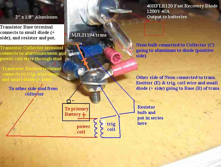
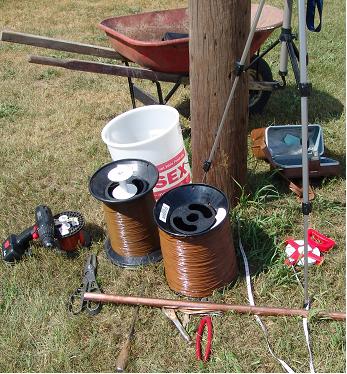
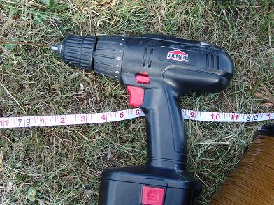
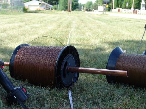
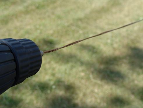
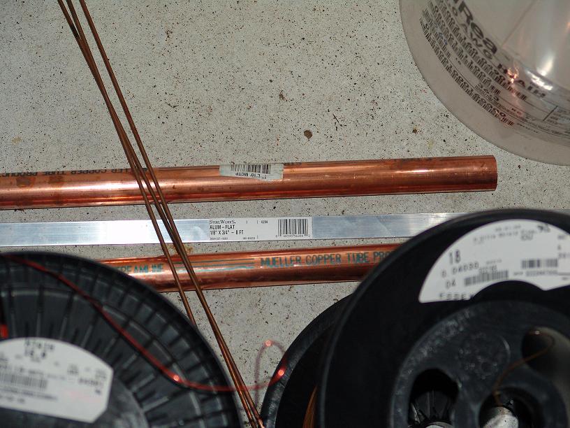
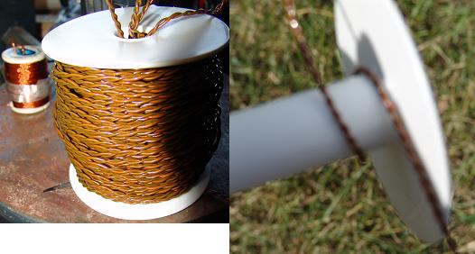
INTRODUCTION TO THIS PAGE: THIS PART BELOW IS OLD AND COULD NEED UPDATES. On this page we will show the progress, pictures, and videos of the complete construction and testing of the Group Project 1 Bedini Monopole Simplified School Girl (SSG) and Bedini Trifilar medium scale Setups. I will try and make a more comprehensive introduction to what these are in the near future. Basically these are very good battery chargers that also power a small load while charging. Two of the easiest ways to make battery chargers in the world; yet you will not find any others that are better. I showed a few months back on the main page how the smaller setup displayed unusual phenomena that makes it worthy to investigate. The inventor, who has several patents on this technology, gave these simple plans for people to study this phenomena. The more people experiment and study this setup the more they will learn how to make it bigger and power very useful loads. This Project 1 will become bigger and bigger as we progress. At first we will start with a basic two wire (bifilar) one coil setup and progress eventually to 6 coils with the rotor we are using. PICTURES OF THE PARTS AND CONSTRUCTION PROCESS. Sorry I can't show all the pictures on one page, it just would take up too much bandwidth. So just right click each link and choose "open in new window" to see each picture (or hold the shif key down and left click the link): The basic circuit setup on aluminum bar mounting. You can see in the picture the construction of the mounting of the transistor on the aluminum. Between the transistor and the 1/8" aluminum is oxy electrical contact grease (not transistor grease). All the connections have this grease on them to help transfer energy better. The transistor is a MJL21194 (250V 16A) (see the specs in the files section on the Bedini_Monopole list. The diode is a40HFLR120 Ruttonsha (1200V 40A Fast recovery). Also a neon bulb. Here are the batteries and battery wires I'll be using with temperary rotor (26 2" Radio Shack Ceramic 5 magnets doubled to make 52, on a plastic 17" wheel]. The 10 batteries are the U2200 Interstate 6V golf cart batteries which are very worn used batteries. The wires are rated 2/0 and are about one inch thick. The magnets on the new rotor will be from http://www.magnetsales.com They are 2.95" x 0.95 (15/16") x .5" Here are my tools and parts to twist the coil wires and wind the coil (by hand and drill). This is not easy work, but I had no problem with either the big or small coil this time. I tied the wires to one pole and measured out 170' with tape. Then I ran the wires (#15 and #18) to 180'. All I need was 170' but I did not know if it would break. Which it did once while winding, but only a little bit came off (less than one foot). I have to check the resistence on the larger #15 ga. wire so that it is around 0.54 ohms for matching with the transistor. Yes those are 92 lb spools of wire run on the freshly cut grass. I put several of these large spools and a bike along the path to hold up the wires while I twisted them. I cut the wire off at 180' and put the ends in the drill and twisted for over half an hour. It broke once at the start (happens more if you pull too hard while twisting). It shortened my length about 10 feet; but could have shortened more if I twisted it more. This is the wire specks and some copper and aluminum bus bars. This is the coil after and before it was fully wound. Two wires twisted (like litzing wires). The wires fill the spool about 3" in diameter. More pictures and video will be added of this building in time. PROGRESS REPORTS DATED: July 7, 2005: I twisted the wires and wound the coil, and have the basic circuit ready to hook up. I still need the coil core material and the rotor. While waiting for that I'll use nother rotors with 2" magnets. I may test out an air core coil also. The coming rotor is 6" in diameter and 3" wide and made out of aluminum.
SEE OLDER PAGE FOR PROJECT TWO CONSTRUCTION AND TESTING
truthinheart.com/JohnBedini.html Copyright (c) 2004-7 Truth In Heart. |